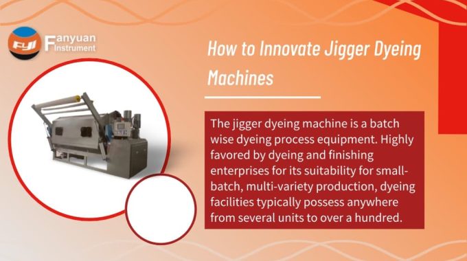
How to Innovate Jigger Dyeing Machines
The jigger dyeing machine is a batch wise dyeing process equipment. Highly favored by dyeing and finishing enterprises for its suitability for small-batch, multi-variety production, dyeing facilities typically possess anywhere from several units to over a hundred.
Contents
Industry Background and Innovation Drivers
In recent years, water intake standards in the dyeing and finishing industry have restricted the application of high-liquor-ratio jet dyeing machines in immersion processes. Furthermore, new market access conditions for printing and dyeing stipulate that “batch dyeing equipment must achieve a liquor ratio below 1:8 (1:10 for silk and wool dyeing)”. Consequently, jig dyeing machines, with their typical liquor ratio around 1:3, show a growing trend of replacing jet dyeing machines. This presents both an opportunity and a test for jigger machine manufacturers. It is crucial to innovate jigger machines to contribute to product enhancement, energy conservation, and emission reduction for dyeing and finishing enterprises. The following discussion explores how to innovate jigger dyeing machines.
Market Status and Price Paradox of Jigger Dyeing Machines
Current market prices for jigger dyeing machines vary significantly. While the adage “you get what you pay for” holds, the practical differences in process applicability, product quality, and production cost between machines costing tens of thousands versus hundreds of thousands of RMB per unit must be evaluated. This requires comparison across multiple factors: production efficiency, first-pass success rate, presence of batch-to-batch shade variation, side-to-center shade variation, lot-to-lot difference, and consumption of water, electricity, steam, dyes, and auxiliaries, as well as finished product quality. If the performance, cost, and quality delivered by a ¥60,000-70,000 machine are not significantly inferior to those of a ¥300,000 machine, it indicates fundamental flaws in the overall design or process application of jigger machines.
High-priced jigger machines in the market are often promoted as “giant” units with 1400 mm diameter rolls, typically featuring dual-frequency conversion (or servo drive), constant linear speed, constant tension, and PLC control. However, production practice reveals that rolls exceeding 1200 mm diameter are rarely used. The reason is simple: larger diameters increase the risk of end-to-end and side-to-center shade variation, forcing manufacturers to sacrifice processing efficiency and increase batch numbers to avoid defective cloth. In theory, maintaining a fixed micro-speed difference between unwinding and winding should ensure constant tension. If overall tension is controllable and the fabric maintains uniform pickup during winding, end-to-end and side-to-center shade variation should not occur. The market’s “peculiar phenomenon” – buyers unwilling to invest in “high-end” jigger machines, preferring cheaper models for lower-grade textiles – indeed suggests problems with high-end machine technology. Buyers are price-sensitive based on quality, and their choices are mostly rational.
This “peculiar phenomenon” is undesirable. It hinders textile quality improvement and promotes excessive production of low-to-medium grade textiles, which harms the sustainable development of the dyeing and finishing industry. How can “high-end” jigger machines be innovatively redesigned to produce high-quality textiles while conserving energy and reducing emissions?
Analysis of Shade Variation Causes in Large-Diameter Rolls

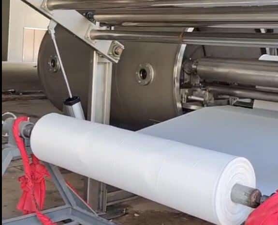
Conventionally, larger roll diameters lead to tension changes due to deviations in the unwinding/winding speed difference from the set value, causing end-to-end shade variation. But why does practice indicate “diameters above X mm cause side-to-center shade variation”? On-site observation reveals that when winding diameter exceeds 1000 mm, a “mustache-shaped” zone with reduced liquor runoff appears in the fabric center. Exceeding 1200 mm, this low-runoff zone expands into a “trapezoid”.
Liquor runoff from the winding roll during processing is a squeezing effect between layers; runoff volume is proportional to tension. Uniform runoff across the width reflects uniform crosswise pickup. The “drying” in the “mustache” and “trapezoid” zones highlights lower pickup in the fabric center, with pickup gradually increasing towards the selvedges as diameter grows. Larger diameter changes cause more severe side-to-center shade variation, directly linked to larger tension variations with diameter change.
Tension in the jigger process arises from the linear speed difference between winding and unwinding, friction during fabric guiding, and tension frame-induced fabric elongation (elastic deformation).
According to Hooke’s Law, fabric tension F is:
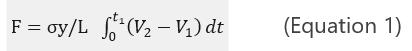
Where:
σ = Fabric cross-sectional area;
y = Fabric elastic modulus;
L = Distance between drive points;
t₁ = Machine start-up time;
V₂ = Winding linear speed;
V₁ = Unwinding linear speed.
Equation 1 shows that fabric tension regulation is an integral process. Clearly, any fluctuation in V₁ or V₂ during steady-state operation will cause tension fluctuation.
The jigger system is a typical nonlinear time-varying system. Let the fabric elasticity coefficient be K_F. According to Hooke’s Law:
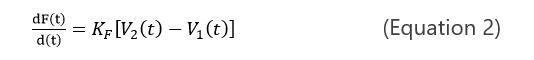

In Equation 3, t_f is the time for fabric to travel from the unwind roll to the wind roll, and ΔL(t_f) is the elongation between drive points.
Therefore, if V₂(t) – V₁(t) remains constant throughout winding (i.e., constant linear speed at drive points), then dF(t)/dt = 0, meaning tension is constant. This indicates the tension control system is subordinate to a linear speed following system. From a fabric length perspective, ΔL(t_f) should be constant, making the tension control system also a position servo system.
Do current jigger machines employ linear speed following or position servo systems?
Defects in Existing Tension Control Technologies for Jigger Dyeing Machines
Unwind and wind rolls must operate according to the winding mechanical characteristic curve (a hyperbola) during the process. Fabric thickness varies. Under constant winding speed, the time required to achieve the same diameter increment differs significantly from small to large diameters. To maintain constant linear speed, the instantaneous diameter must be known to adjust motor speed accordingly. Conventional diameter measurement primarily uses three methods:
Linear Speed Calculation Method
Uses a tension-control capable frequency converter. The PLC sets the process tension, and a linear speed sensor provides feedback to adjust the wind/unwind motor speed for constant fabric speed. However, this method requires memory of pre-stop operating parameters. Furthermore, fabric slippage (“lost turns”) on the measuring roller of the speed sensor causes inaccurate speed signals, especially due to varying fabric thickness, tension changes, and inconsistent swelling after liquor absorption. Using only the converter’s internal tension module offers poor control accuracy (5%-10%), insufficient for shade variation prevention.

Thickness Integration Method
Calculates instantaneous diameter based on lap counting signals. Controllability is poor because fabric thickness is an uncertain variable.
Direct Diameter Measurement Method
Uses touch rods, ultrasonic sensors, or CCD pattern sensors for real-time diameter measurement. While diameter is measured accurately, control linearly adjusts motor speed with diameter change, which does not conform to the winding mechanical characteristic curve. Consequently, linear speed deviates from the set value during most of the diameter change process.
In summary, existing constant linear speed and constant tension control devices/technologies in jigger machines suffer from poor control accuracy and non-conformance to the winding mechanical characteristic curve. The lap counting method’s inability to determine processed fabric thickness onsite is the root cause of end-to-end and side-to-center shade variation defects observed in current “giant” jigger machines.
Innovative Solution
It is reported that patented tension control technology conforming to the winding mechanical characteristic curve is available for direct application in jigger machine innovation. This mechatronic device features:
A direct diameter measurement sensor. Mechanical memory function during stops for easy restart at process speed. Standard, mature electronic sensors with high output precision, waterproofing, heat resistance, and anti-interference. An excitation board designed according to the roll build-up during jigger processing, generating the characteristic curve Uk = f(D). This controls constant unwinding/winding linear speed while maintaining controllable tension.