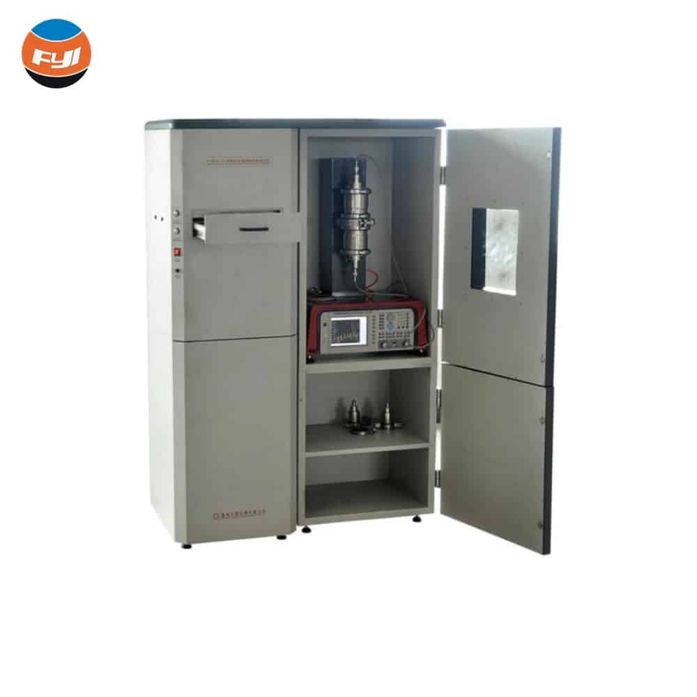
Introduction of Fabric Anti-Electromagnetic Radiation Performance Tester
Fabric anti-electromagnetic radiation performance tester is used to solve the testing problem of textile materials. Fabric anti-electromagnetic radiation performance tester is used to measure the electromagnetic wave protection ability and electromagnetic wave shielding ability of textiles, plastic cloths, metal sheets, etc. So as to achieve the electromagnetic radiation protection effect of textiles comprehensive evaluation.
Contents
Background
Electromagnetic radiation is composed of electrical energy and magnetic energy which is transferred together through space. This energy is generated by the movement of electric charges. For example, the moving electric charges emitted by a radio frequency antenna are transmitting a signal which will produce electromagnetic energy. The electromagnetic “spectrum” includes all kinds of electromagnetic radiation, from extremely low frequency electromagnetic radiation to extremely high frequency electromagnetic radiation. There are also radio waves, microwaves, infrared rays, visible light and ultraviolet light in between. The general definition of the radio frequency part of the electromagnetic spectrum refers to radiation with frequencies ranging from approximately 3kHz to 300GHz. Some electromagnetic radiation has certain effects on the human body.
In the process of traditional fabric anti-electromagnetic radiation performance testing, the fabric will be pressed tightly. When the fabric is in a squeezed state, the textile fibers inside it will be stacked. And the surface area for absorbing electromagnetic radiation will be reduced, which will affect experimental accuracy. If the fabric is not pressed tightly, part of the electromagnetic radiation will pass through the remaining space and be diffracted to the outside world without decay. It will have a certain impact on the human body during the long-term detection test. At the same time, the remaining space will also will affect time accuracy.
Test principle
The basic principles of electromagnetic shielding effectiveness:
Reflection: Shielding materials can reflect electromagnetic waves. Electromagnetic waves are reflected after hitting the surface of the material and will not penetrate the material.
Absorption: Part of the electromagnetic wave energy is absorbed by the material and converted into heat energy. This reduces the propagation of electromagnetic waves.
Transmission: A material can allow some electromagnetic waves to pass through, but usually weakens the intensity of the electromagnetic waves.
Flange coaxial method
The applicable frequency range of the flange coaxial device test method is 30 MHz~3 GHz. The basic principle is to set up a receiving antenna in the electromagnetic wave detection device to measure the electromagnetic waves caused on the surface of the object being measured. During the test, the orientation and position of the antenna remain unchanged. When the distance between the antenna and the measured object is changed or the distance between the measured objects is changed, the changes in the detected electromagnetic wave signal are recorded. And then record the Electromagnetic shielding effectiveness. When using the flange coaxial method to measure electromagnetic shielding effectiveness, a metal plate with a certain thickness needs to be placed between the measured object and the detection equipment to achieve the shielding effect. During the test, the shielding degree is simulated by changing the number and position of the partition plates in the metal plate. And then the changes in the electromagnetic wave signal are observed to calculate the electromagnetic shielding effectiveness.
Shielding box method
1) The shielding box is a method of confining electromagnetic waves to a certain area through shielding bodies such as shells, boxes, and plates made of metal. Radiation sources are divided into electric field sources in the near area, magnetic field sources, and plane waves in the far area. Thus, the shielding effectiveness of the shield varies according to the radiation source, in terms of material selection, structural shape, and hole leakage control.
2) To achieve the required shielding effectiveness during design, it is necessary to confirm the radiation source and clarify the frequency range firstly. Then confirm the control factors based on the typical leakage structure of each frequency band. And select appropriate shielding materials and design the shielding shell. Electromagnetic shielding is to use a shield to isolate two spatial areas to control the induction and radiation of electric fields, magnetic fields and electromagnetic waves from one area to another.
3) Magnetic field shielding usually refers to the shielding of static magnetic fields or alternating magnetic fields. The principle of magnetic field shielding is the shield provides a low magnetic resistance magnetic path to the interfering magnetic field. Thereby shunting the interfering magnetic field. It can be understood as providing a bypass for the interference magnetic field to pass without affecting the inside of the shield.
4) When the electromagnetic wave reaches the surface of the shielding body, due to the discontinuous impedance on the interface between air and metal, the incident wave is reflected. This reflection does not require the shielding material must have a certain thickness. But this reflection only requires the interface between the air and the metal does not have a certain thickness discontinuous. The energy that is not reflected from the surface and enters the shielding body is attenuated by the shielding material during the forward transmission in the body.
Fabric anti-electromagnetic radiation performance tester features
- LCD screen display.
- Simultaneously satisfy flange coaxial method testing and shielding box method testing.
- Equipped with a metal shielding device, a shielding observation window is provided on the device.
- The clamping method adopts pneumatic operation which is convenient and fast. Avoiding the difference in test results caused by different pressures on the specimens caused by manual operation.
- The shielding box is made of SUS304 stainless steel, which is corrosion-resistant and rust-free.
- Up and down mechanisms are driven by alloy lead screw and guided by imported guide rails to ensure that the conductor clamping face accurate docking.
- The host conductor is made of high-quality alloy steel, with a nickel-plated surface, which is strong and durable.
- Use high-precision network analyzer and multi-channel detection loop.
- Test data and graphics can be printed out through online software.
- The instrument is equipped with a communication interface which can dynamically display graphics when connecting to a PC. Special test software can eliminate system errors (normalization function can automatically eliminate system errors).
- Provide SCPI command set and provide technical support for secondary development of test software.
- The number of frequency sweep points can be set, up to 1601.
Technical parameters
| Frequency range | Shielding box method: 300kHz~30MHz Flange coaxial method: 30MHz~3GHz Antenna: 100kHz to 30MHz |
| Characteristic impedance | 50Ω |
| Voltage standing wave ratio | Flange coaxial method: <1.2 Network analyzer: <2 |
| Transmission loss | <1dB |
| Test range | ≤95dB |
| Accuracy | 0.01dB |
| IF bandwidth | <1kHz |
| Standing wave ratio | <1.2 |
| Attenuation | ≥7dB (rated power ≥1W) |
| Connector | N type |
| Shielding box size | 1100mm×550mm×1650mm (L×W×H) |
| Shielding box material | high-quality alloy steel |
| The height between the center of the square hole and the ground | 1mm |
| The width of the flange at the edge of the square hole | ≥25mm |
| The flange seat | conductive |
| Antenna type | loop antenna |
| Layout | Using coaxial method or vertical placement. The height of the antenna must ensure that the bottom of the antenna pole is in line with the the bottom of the test window is parallel. |
| Sample size | Flange coaxial method: 133.1mm, 33.1mm, 66.5mm, 16.5mm Shielding box method: 300mm×300mm |
| Dimensions | 1100mm× 550mm×1650mm (L×W×H) |
| Environmental requirements | 23℃±2℃, 45%RH~75%RH |
| Atmospheric pressure | 86~106kPa |
| Power supply | AC220V, 50Hz, P≤113W |