Definition, Function and Instrument of MFI Test
Contents
What is a MFI test?
Melt flow index, is a value that indicates the fluidity of plastic materials during processing. The MFI test method is: first, let the plastic pellets melt into plastic fluid within a certain time (10 minutes), at a certain temperature and pressure (different standards for various materials), and then measure the grams (g) of plastic that flows out through a 2.1mm diameter tube. The larger the value, the better the processing fluidity of the plastic material, and vice versa.
The role of MFI testing
- In terms of quality control on the raw material side, the MFI test constitutes the core indicator of thermoplastic feed inspection. Due to fluctuations in the molecular weight distribution, additive ratio and degree of polymerization of different batches of resins. The consistency of the flow properties of the raw materials can be effectively monitored by measuring the extrusion weight of the material within 10 minutes using a standardized tester (the test conditions are usually 230°C/2.16kg or material-specific standards). Taking polypropylene (PP) production as an example, if the MFI value of different batches of the same brand fluctuates by more than ±15%, it is judged as abnormal quality, and the polymerization reaction conditions or granulation process parameters need to be traced. This quantitative control method can avoid molding defects such as flash and short shots of injection molded parts caused by differences in raw material fluidity, and ensure the stability of the supply chain.
- In the engineering material selection during the product development stage, MFI data is a key parameter for material engineers to match performance. Different application scenarios have different requirements for material flow characteristics: thin-walled products (such as mobile phone cases) require fast-filling mold materials with higher MFI values (30-50g/10min). Structural parts that are subjected to mechanical stress (such as car bumpers) tend to choose high-strength materials with lower MFI values (5-15g/10min). By establishing a correlation model of MFI-tensile strength-impact toughness, the mechanical property attenuation curves of materials with different flowability can be systematically evaluated, providing data support for the optimal material selection under specific working conditions.
- In the process of setting molding processing parameters, the MFI value directly affects the determination of the injection molding process window. According to the Arrhenius equation, melt viscosity is exponentially related to temperature, and MFI essentially reflects the apparent viscosity under specific temperature and pressure conditions. Process engineers can reversely deduce the n value (non-Newtonian index) and K value (consistency coefficient) in the melt flow equation based on the MFI test value. Then optimize key parameters such as injection pressure (usually controlled at 70-150MPa), melt temperature (conventional range 180-300℃) and holding time. For example, for every 10 units increase in MFI, the injection speed can be reduced by 5%-8%. This can not only ensure the completeness of mold filling, but also reduce energy consumption and molding cycle.
- In the product quality control system, the MFI test can sensitively reflect the degree of material degradation during the processing. The polymer chain will break and degrade under the action of screw shear and thermal history. This structural change is directly manifested as an abnormal increase in the MFI value. By comparing the MFI change rate (ΔMFI) of raw materials and recycled materials, the degree of thermal oxidation aging of the material can be quantitatively evaluated. Taking polycarbonate (PC) as an example, when ΔMFI exceeds 25% of the original value, its impact strength will decay by more than 30%. At this time, the processing temperature must be adjusted or stabilizers must be added. This online monitoring method is particularly important for fields that are sensitive to material properties, such as medical-grade plastic products and optical components.
ASTM D-1238: Standard Test Method for Melt Flow Rates of Thermoplastics by Extrusion Plastometer
ISO 1133: Plastics — Determination of the melt mass-flow rate (MFR) and melt volume-flow rate (MVR) of thermoplastics
GB 3682-83: Test method for melt flow rate of thermoplastics
JIS K7210: Plastics – Determination of The Melt Mass-flow Rate (MFR) And Melt Volume-flow Rate (MVR) Of Thermoplastics – Part 1: Standard Method
DIN 53735: Testing of Plastics: Determination of The Melt Flow Index of Thermoplastics
BS 2782: Methods of testing plastic – Introduction
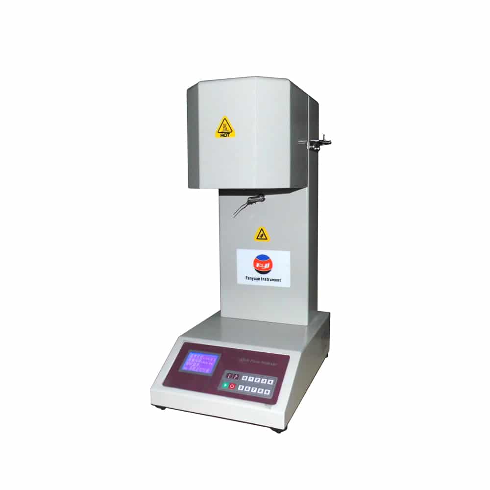
Structure and working principle of MFI Tester
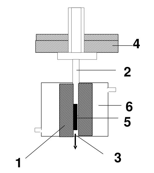
1, barrel,2, piston rod 3, die 4, load, 5, polymer sample 6, temperature control system
Melt flow rate meter is a kind of extrusion plastic meter. It uses a high temperature heating furnace to make the object to be tested reach a molten state under specified temperature conditions. The object to be tested in this molten state is extruded through a small hole of a certain diameter under the load gravity of a specified weight. In the plastic production of industrial enterprises and the research of scientific research institutions, “melt (mass) flow rate” is often used to express the fluidity, viscosity and other physical properties of polymer materials in the molten state. The so-called melt index refers to the average weight of each section of the extrudate sample converted into 10 minutes of extrusion.
Introduction to two measurement methods of melt index tester
Melt index tester is an essential testing instrument for plastic processing enterprises. Commonly used testing methods are melt mass flow rate (abbreviated as mass method or MFR) and melt volume flow rate (abbreviated as volume method or MVR). The following is an explanation of these two MFI test formulas:
MFR (Mass Method)
The melt (mass) flow rate is expressed as MFR, and the unit is: g/10 min
The formula is: MFR(θ 、 mnom )=tref*m/t
Where:
θ —— test temperature
mnom—— nominal load Kg
m —— average mass of cut-off g
tref —— reference time (10min), S (600s)
t —— time interval of cut-off s
Example: A group of plastic samples, a section is cut every 30 seconds, and the mass of each section is: 0.0816 g, 0.0862 g, 0.0815 g, 0.0895 g, 0.0825 g.
Average value m = (0.0816 + 0.0862 + 0.0815 + 0.0895 + 0.0825) ÷ 5 = 0.0843 (g)
Substitute into the formula: MFR = 600 × 0.0843/30 = 1.686 (g/10 minutes)
MVR (Volumetric Method)
The melt volume flow rate (MVR) value is calculated using the following formula, in cm³/10min.
MVR (θ, mnom) =A*tref*l/t=427*l/t
Where:
θ is the test temperature, ℃
mnom is the nominal load, kg
A is the average cross-sectional area of the piston and the barrel (equal to 0.711 cm³),
tref is the reference time (10min), s(600s)
t is the predetermined measurement time or the average value of each measurement time, s
l is the predetermined measurement distance moved by the piston or the average value of each measurement distance, cm.