How to do Filament Yarn Strength Test?
How to do Filament Yarn Strength Test? The automatic single yarn strength tester will help you.
Contents
What is Automatic Single Yarn Strength Tester
Automatic single yarn strength tester, which is controlled by PC, is used for determining the physical characteristics of single yarn or filament. Such as breaking force, elongation at break, breaking tenacity, time-to-break and force-elongation curve. The tester is integrated with an PC that is equipped with Windows operating system, color display, keyboard, mouse and printer. So that data acquisition, calculation and output are fully automatic.
Tester composition and working principle
YG023B automatic single yarn strength tester is composed of the main unit, printer, yarn creel, display, etc, which outside view is shown in (Fig 1).
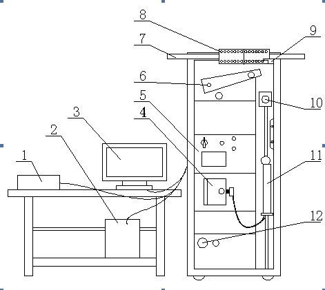
Fig. 1 Schematic Outside View of YG023B Automatic Single Yarn Strength Tester
| 1. Printer | 2. computer | 3. Display | 4. Suction box |
|---|---|---|---|
| 5. Control box | 6. Manipulator | 7. Head traverse bar | 8. Front guide rack |
| 9. Scissor | 10. Upper clamp | 11. Lower clamp | 12. Manometer |
The main unit is built with a cabinet structure, which contains IPC chassis, transmission system, force measuring system, length measuring encoder and drive circuits.
The IPC chassis includes: IPC rack, PIII industrial mother board, dada acquisition card, I/O card, hard disk, CD-ROM and floppy disk drive.
The data acquisition card is provided with software programming function for gain control so that it is possible for the tester to realize graduation function for force values by means of a sensor.
The transmission system is provided with an imported AC servo drive and an AC servo motor (with built-in tacho-generator). By way of a gear reduction unit, the motor shaft output drives the chain that is connected with the lower clamp. Therefore, the vertical movement of the lower clamp is realized smoothly by controlling the motor rotation at constant speed in positive and reverse directions.
Force is measured by means of a four bar linkage mechanism. The upper clamp, which is provided with counterweight and damper at its rear, presses against the sensor probe through a hanging plate. The accuracy of force measurement is ensured by the counterweight that balances the four bar linkage mechanism and the damper that prevents the four bar linkage mechanism from shaking during its movement.
The rear end of the gear reduction unit of the tester is connected with a high-precision encoder, which output impulse signal is much smaller than the ±1mm elongation tolerance, so that the accuracy of length positioning and elongation measurement is guaranteed.
The drive circuits include sensor amplifying circuit and I/O signal interface circuit, which mainly control six electromagnetic air valves, manipulator drive, yarn feeder rack drive, as well as button signal and limit switch signal.
How to do Filament Yarn Strength Test?
Automatic testing:
Set up test parameters as the first step and then install the specimen.
Press “START” button on the operating panel. The manipulator returns to the lowest position. And the lower clamp goes up to the top at the max speed until it touches the upper limit switch.
The specimen is clamped and a downward movement follows. The moment for it to leave the upper limit switch is taken as the initial point of length measurement. The number of encoder impulse is registered so that the lower clamp stops moving when it reaches at the preset gauge length.
Now the manipulator grips the specimen to apply pretension and the upper clamp closes by suction. The lower clamp draws at the preset speed and the load cell is applied by force. The computer registers the force value of the load cell and the elongation value of the encoder, which are sent to the screen for display and plotting a force-elongation curve.
When a cycle of drawing is completed, the computer processes the registered values to get the data of breaking force, breaking tenacity, breaking elongation, elongation at break, work done, time-to-break, elongation at specified force, force at specified elongation, etc. The remaining yarn after breaking is automatically collected by suction into the suction box.
Then the tester repeats the above cycle for the next test. When a bobbin is completely tested, the front guide rack moves one step to the right side and the pneumatic scissor cuts off the previous yarn. Then the manipulator goes up to the highest position to pick up the next yarn for testing. The tester stops operation as soon as tests are completed entirely. When “Data Statistics” is clicked, the single test value and the max., min., mean and CV% values of the test data will be displayed. The user may choose printout or data saving.
As for fiber factory or lab research .They should know their sample is filament or staple fiber. Thus we can recommend the correct model the correct model with correct clamp .
if you need more information please send email to [email protected]


Comments are closed.
The procedures are explained in great detail.