
Roving Frame Workflow and Related Calculation
As an important production equipment of cotton mill, roving frame belongs to the preparation process from combed sliver to spinning into yarn in the production process. Roving production is the last of the preparatory stages for spinning.
The tasks of the roving production
(1) Drafting the sliver to a finer one whose weight per unit length is made to allow a draft at the ring frame in the approximate range of 4 to 12;
(2) Using two suspended flyers to inserting few twists to the roving to make it strong enough to sustain the tension in further processing;
(3) Winding roving into the bobbin in proper way.
Contents
Drafting
The drafting system is the key to the rubbed roving frame, which adopts 3- roller -2-apron drafting arrangement can make the friction boundary distribution reasonable, the floating zone is small, can effectively control the fiber movement, the total draft multiple is high, and the roving eveness is good.
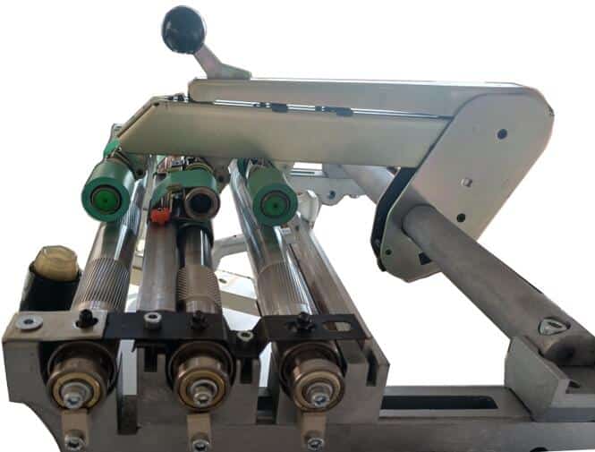
Illustrations of 3- roller -2-apron drafting systems for a roving machine
The bottom rollers are fluted steel and the top rollers are covered with synthetic rubber. When the top pendulum is latched down, springs are, compressed to apply pressure on the top rollers for good, strong contact with the bottom rollers. Located in the front draft zone are top and bottom aprons, necessary to suppress drafting waves caused by roller drafting.
Drafting roller spacing is the distance between the nip lines of successive roller pairs. This distance, as with all roller drafting systems, is adjustable to accommodate the fiber length to be drafted. Total draft is determined by the surface speeds of the back and front roller pairs. The draft in the back zone is referred to as break draft, and it should be as low as feasible so that the largest portion of the total draft will take place in the front zone where apron control of fiber movement is located. Most roving frames are designed to allow a large range in total draft from 4 to 20 and above. A more practical range 4 to 12 has been found to yield a better quality product.
Twisting
The suspended flyer is a twisting mechanism, and the suspended flyer turns once and adds a twisting. Doffer does not need to pull out the flyer, easy to operate, reduce the work intensity, is conducive to automation. Good rigidity, high rotation stability, suitable for high speed and large roll.
Twist multiple in roving should be sufficient to prevent stretching of the strand in normal handing and in its travel in the spinning creel. The method of calculating the twist in roving is to relate flyer speed to the velocity of the strand exiting the front roller:

In roving production, a combined twist insertion and bobbin build device is used to insert twist to the attenuated strand, and wind the roving into the bobbin.
Winding
This roving frame adopts bobbin guide winding (nb>ns, b-bobbin, s-spindle). The roving is coiled in a circle around the bobbin cylindrical winding surface, and the height of the yarn layer decreases from inside to outside, forming a truncated cone at both ends and a cylinder in the middle.
The roving, which is threaded through the hollow of the fly and around the presser arm, is pulled and wound onto the bobbin by the rotation of the hollow spindle. To do so, the bobbin, which rotates with the hollow spindle, runs at a higher rotational speed than the flyer. This is referred to as winding-up by bobbin lead. If the bobbin rotates at speed Nb, and the spindle at Ns, then the winding-up speed Vw is given by
Vw=πDb(Nb-Ns)
Where Db is the bobbin tube diameter at the instant of winding.
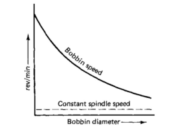
During winding, there must be a balance between the wingding-up speed Vw, and the delivery speed Vd, at which the drafted ribbon leaves the front drafting rollers. Therefore, as the bobbin diameter increases with the number of roving layers wound onto the bobbin, the bobbin speed must decrease.
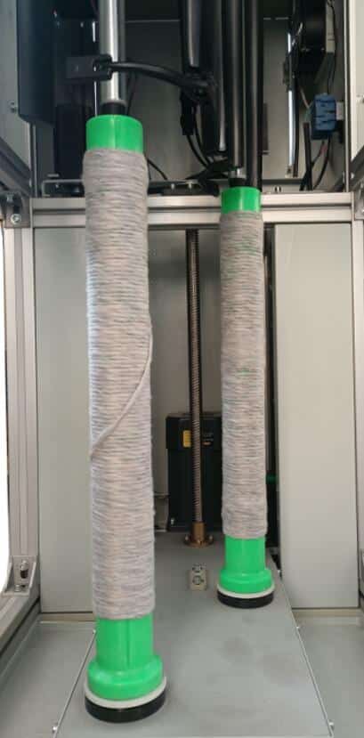
A roving bobbin is a cylindrical body with tapered ends. The tapers at both ends of the bobbin are formed by the reduction in the length of the wind traverse after each full layer of roving has been made. In order to be able to wind over the whole length of the tube, the winding point must be continually shifted. To do so, the lead screw lifts and lowers the bobbin past the presser arm to build successive lavers of roving coils.
Each layer of roving wound onto the package cause an increase in diameter. As mentioned above, for bobbin lead winding-up, the speed of the lead screw, and also of the bobbin itself, must be continuously reduced.
Vh=Nw*hn
Where Vh is the velocity of the leas screw,
Nw is the bobbin tube speed at the instant of winding,
hn is the axial winding distance.
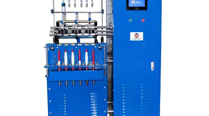
DW7030H uses PLC as the core control, connects the frequency converter to control the speed of the motor, makes the motor run synchronously, makes the tension of the yarn stable, and adjusts the speed of each motor according to the change of the winding diameter of the yarn, so that the entire transmission system is coordinated.
By using computer control technology, programmable control technology and variable frequency technology, the traditional roving frame forming mechanism, upper and lower cone wheel mechanism, cone wheel automatic reset mechanism and tension fine-tuning structure are cancelled, and the mechanical structure is greatly simplified.
Using a large contact display that can simply set the carrying conditions, as long as the necessary parameters are directly input on the screen, such as: roving quantity, fiber variety, winding coefficient, twist, fixed length, spindle speed and other basic spinning conditions, the speed relationship of each motor can be automatically set by the computer through a mathematical model. With the increase of the number of spinning layers, the spindle wing speed is automatically adjusted to make the roving tension and winding state best. Thus reduce the ding fracture, improve the operating efficiency and operational efficiency.
Comments are closed.

That being said, the blog could have benefited from more diverse perspectives and counterarguments.
Those looking for a fresh perspective on the topic will not be disappointed by this blog post.
About time I came across such a well-researched piece! The author left no stone unturned in presenting the facts.
Read it, see it, believe it! This article offers a fresh perspective on a familiar subject.
Hey, fellow enthusiasts! Join me in praising this incredible piece of writing – it’s a game-changer.
Can’t get enough of this author’s writing! Each article they produce is a gem of knowledge and inspiration.