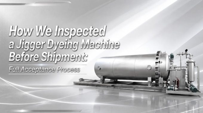
How We Inspected a Jigger Dyeing Machine Before Shipment: Full Acceptance Process
A recent acceptance test was conducted on an atmospheric-pressure jigger dyeing machine, comprehensively covering the entire process—from mechanical structure, valve systems, and piping seals to motor operation and final rectification. Unlike a simple pre-shipment confirmation, this inspection was closer to a system-level evaluation under real operating conditions, focusing on identifying potential risks in advance and verifying the machine’s stability in practical use.
Through on-site measurements, pneumatic testing, no-load motor operation, and issue rectification, it becomes possible to assess the equipment’s reliability in future dyeing production more clearly. It also reflects the level of process control and attention to detail during manufacturing.
Contents
Inspection Preparation
Mechanical structure

| (1) | Foot Margin | (2) | Vessel Head System |
| (3) | Outer Cylinder Head Structural Parts | (4) | Lock Ring System |
| (5) | Vessel System | (6) | Trough |
| (7) | Service Tank | (8) | Unloading Device |
Inspection Tool
To ensure that the inspection of the jigger dyeing machine proceeded efficiently and in an organized manner, a comprehensive checklist of inspection items was compiled and prepared well in advance of our departure. Many issues encountered during inspections do not stem from a lack of technical competence on-site, but rather from inadequate preparation beforehand—leading to situations where critical dimensions cannot be measured, specific details cannot be verified, and necessary corrective actions cannot be properly documented. This is particularly true for large-scale dyeing and finishing machinery like the jig dyeing machine, which involves numerous complex aspects—including mechanical components, electrical systems, piping, rollers, welding integrity, leveling, and assembly precision—necessitating the presence of a wide array of measurement, documentation, and temporary repair tools at the inspection site.
For this business trip, in addition to gathering essential documentation—such as the machine acceptance checklist, operational drawings, purchase orders, and key execution guidelines—we also brought along a suite of precision measuring instruments. These included tape measures, steel rulers, vernier calipers, dial indicators, spirit levels, and thread gauges, which were utilized to verify critical dimensions, assembly accuracy, and operational stability. Concurrently, we packed a basic toolkit—comprising hex keys, open-end wrenches, and screwdrivers—to facilitate on-site disassembly for detailed examination and the adjustment of minor issues. Furthermore, anticipating the possibility of minor surface rust, scratches, or packaging damage occurring during the manufacturing and transit phases, we prepared supplementary supplies—such as sandpaper, rust-inhibiting lubricants, adhesive tape, and stretch wrap—to facilitate temporary repairs and to verify the proper rectification of any identified defects.
In many instances, true professionalism is not demonstrated through verbal descriptions alone; rather, it is reflected in one’s ability to know precisely *what* to inspect on-site, *why* those specific items require inspection, and—upon discovering a defect—how to accurately assess the extent of its potential impact. Ultimately, the thoroughness of the preparation undertaken during the pre-inspection phase serves as the decisive factor in determining the professional depth and effectiveness of the subsequent inspection process.
| No. | Item Name | Quantity |
| 1. | Jigger Acceptance Sheet | 2 copies |
| 2. | Operation (OP) Drawings | 1 copy |
| 3. | Key Implementation Points | 1 copy |
| 4. | Purchase Order | 1 copy |
| 5. | Utility Knife | 1 pc |
| 6. | Scissors | 1 pair |
| 7. | 3M Adhesive | As required |
| 8. | Marker Pen | 2 pcs |
| 9. | Adhesive Tape | 2 rolls |
| 10. | Stretch Wrap Film | 1 roll |
| 11. | Tape Measure | 1 pc |
| 12. | Steel Ruler | 1 pc |
| 13. | Vernier Caliper (200mm) | 1 pc |
| 14. | Leveling Instrument | 1 pc |
| 15. | Dial Indicator with Magnetic Base | 1 pc |
| 16. | Thread Gauge | 1 pc |
| 17. | Hex Key Set | 1 set |
| 18. | Open-end Wrench Set | 1 set |
| 19. | Screwdriver Set | 1 set |
| 20. | Gloves | 6 pairs |
| 21. | Cleaning Cloth | 2 pcs |
| 22. | Sandpaper (for rust removal) | 1 sheet |
| 23. | Anti-rust Lubricant | 1 bottle |
| 24. | Viscometer Nameplate, Shipping Marks, and Acceptance |
Key Inspection Process
Dye Vat
Following the initial internal inspection of the dye vat, the primary focus shifted to the examination of various cloth guide rollers, the main roller, and the internal piping system. During the actual operation of a jig dyeing machine, the fabric remains in continuous contact with the roller surfaces; consequently, the presence of burrs, scratches, uneven welds, or excessive deviations in concentricity on the roller surfaces can easily lead to fabric abrasion, misalignment, or wrinkling—issues that, in severe cases, can compromise the dyeing quality of the entire batch. Therefore, the inspection of the roller assembly constitutes one of the most critical stages in the overall equipment acceptance process.

On-site personnel began by verifying the dimensions and materials of all internal cloth guide rollers, upper guide rollers, and the main roller within the dye vat. This verification encompassed parameters such as outer diameter, width, quantity, shaft end dimensions, and center-to-center distances, with each item cross-referenced against the engineering drawings and procurement specifications. Subsequently, dial indicators were employed to assess the concentricity and parallelism of the rollers, confirming the absence of any significant run-out during rotation. Particular attention was paid to the main roller; given its substantial size and its pivotal role in driving the fabric’s movement, it demands an exceptionally high level of operational stability. On-site inspectors manually rotated the main roller to observe the smoothness of its rotation, checking for any signs of wobbling, abnormal noises, or rotational resistance, while simultaneously verifying the proper installation of the bearing housings and the precision of the coupling alignment.
In addition to dimensional and operational checks, the surface finish of the rollers constituted a key focus of this inspection. As the interior of a jig dyeing machine is constantly exposed to a high-temperature, high-humidity, and chemically active environment, the surface smoothness of the rollers directly impacts the fabric’s running tension and overall surface quality. During the on-site inspection, it was noted that while the surfaces of certain main rollers had undergone initial polishing, localized areas still exhibited faint machining marks and minor surface roughness. To prevent potential friction-induced damage to the fabric during subsequent processing, the inspectors performed a secondary sanding treatment on these specific areas of the main roller to achieve a smoother finish, while also re-confirming the flatness of the weld transition zones.

Concurrently, a comprehensive inspection was conducted on other internal components of the dye vat—including heating pipes, rinsing pipes, and tension frames—to verify parameters such as hole diameters, hole spacing, installation heights, and surface finishes. Particular emphasis was placed on the uniformity of the perforations in the heating and rinsing pipes, as this directly influences the efficiency of the dye liquor circulation and the uniformity with which the fabric absorbs the liquid. If local aperture deviations are excessive or their alignment is inconsistent, issues regarding localized uneven dyeing are prone to arise during actual production. Consequently, the on-site inspection involved not only dimensional measurements but also placed particular emphasis on assessing the quality of pipe welding, the orientation of the apertures, and the overall levelness of the installation.
Many equipment-related issues do not immediately manifest under no-load conditions. A truly professional inspection entails more than simply verifying whether the equipment “spins”; rather, it requires anticipating future operational conditions to proactively identify specific details that could potentially evolve into quality hazards. This is precisely why the on-site team conducted repeated, rigorous checks of the roller surfaces, parallelism, concentricity, and surface finish quality.
Valves and Piping
Following the inspection of the dye tank’s internal rollers and mechanical structures, the subsequent focus shifted to examining the machine’s valve systems and process piping. For a jig dyeing machine, the valve and piping systems effectively determine the equipment’s subsequent performance regarding temperature control, circulation efficiency, steam switching, and overall operational stability. Should a valve malfunction or a pipe develop a leak, subsequent production runs could easily be plagued by issues such as unstable temperature rise, pressure fluctuations, abnormal dye liquor circulation, or even steam leakage. Consequently, this phase of the inspection requires not only verifying the correctness of the installation but—more importantly—validating that the entire system can operate stably over the long term under actual working conditions.
On-site personnel began by conducting a comprehensive, item-by-item verification of every valve on the machine. This included valves for hot water inlet, cold water inlet, circulation water, steam heating, drainage, safety relief, as well as those associated with the chemical mixing tank. This particular machine design extensively utilizes pneumatic angle seat valves, while specific sections of the drainage system employ pneumatic wafer-type butterfly valves, supplemented by check valves and safety relief valves. During the inspection process, particular attention was paid to verifying valve models, nominal diameters, installation locations, mounting methods, and operational logic (open/close sequencing). For instance, some valves are designed to be “normally open” while others are “normally closed”; if a valve is installed incorrectly—or if its control logic fails to align with the programmed sequence—the equipment may suffer from operational errors during subsequent use.
In addition to verifying valve models and installation, every pneumatic valve underwent a functional air-pressure test. By connecting an air compressor on-site, each pneumatic angle seat valve and butterfly valve was individually actuated to assess its performance. Inspectors observed the responsiveness of the opening and closing actions and checked for smooth cylinder movement, while simultaneously looking for any signs of sticking, air leakage, or failure to return to the proper home position. Given that the interior of a jig dyeing machine involves high-temperature steam and pressurized circulation, the stability of valve response directly impacts the precision of subsequent process control; therefore, this pneumatic testing constitutes an indispensable part of the equipment inspection process.

Testing the leak-tightness of the piping system constituted another key priority during this inspection. On-site personnel began by closing every valve within the entire piping network; compressed air was then introduced into the system, and a pressure gauge was monitored to determine if the internal pressure remained stable. A continuous drop in pressure would indicate the presence of a leak somewhere within the system. To further pinpoint the exact location of any issues, inspectors systematically examined every section of the piping—including all flanged connections, weld seams, fittings, and the areas surrounding the valves—using a soap-and-water solution to detect escaping air bubbles. If a continuous stream of bubbles is observed in a specific area, it indicates a leak at that location, necessitating immediate retightening, remedial welding, or sealing.
During the actual inspection process, minor leaks were indeed detected at several pipeline connection points. Although the leakage volume was minimal, if the equipment were to be formally commissioned—operating under high-temperature and high-pressure conditions—such minor issues could easily escalate into significant problems. Consequently, the on-site team required the manufacturer to rectify the identified leak points and, upon completion of these repairs, to conduct a comprehensive pressure-holding test on the entire pipeline system. The complete pipeline system is deemed to have passed acceptance only if the pressure gauge remains stable throughout an extended period of sustained pressure.
Compared to a mere visual inspection, functional valve testing and pipeline leak-tightness testing provide a far more accurate simulation of the equipment’s actual operating conditions. Such tests serve as the most effective indicators of the manufacturer’s assembly quality, welding proficiency, and mastery of process details; furthermore, they constitute a critical basis for predicting the equipment’s future susceptibility to failure.
Electric Motor
Following the inspection of the valves and piping systems, the subsequent phase involves conducting powered-up testing of the machine’s motors and drive systems. In the context of a jig dyeing machine, the motor section serves as the equipment’s power core; critical operations—such as agitation, circulation, chemical dosing, traverse motion, and vat opening—are all driven by these motors. If a motor suffers from internal defects—such as damaged bearings, rotor eccentricity, phase loss, abnormal noise, or gearbox malfunctions—the equipment will inevitably experience operational failures during formal production runs, even if its mechanical structure appears sound. Consequently, the motor “no-load” (idle) running test is a critical item that must be rigorously verified during the equipment acceptance inspection process.
On-site personnel first cross-referenced the model, power rating, and installation location of each motor—including the agitation motor, circulation pump motor, dosing pump motor, traverse motor, and vat-opening motor—to ensure that every component aligned with the original procurement specifications. For instance, while the circulation pump was originally ordered with a power rating of 2.2 kW, the actual on-site configuration was found to be 3 kW; this discrepancy was immediately documented to prevent future inconsistencies between the technical documentation and the physical equipment.
Upon completing these preliminary verifications, all motors underwent a powered-up, no-load running test. During this procedure, the equipment was briefly energized and operated for approximately 15 seconds to observe the motors’ startup performance—specifically checking for issues such as rough starting, abnormal vibration, unusual noises, stalling, rotor-stator rubbing, or excessive heat generation. Since internal damage within many motors often remains undetectable while the unit is static, it is only through actual powered rotation that the integrity of the bearings, rotors, and coupling mechanisms can be accurately assessed.

Compared to static dimensional inspections, powered motor testing is far more effective at exposing latent issues within the equipment. Although the external appearance of many machines may appear flawless, internal damage caused by transit impacts, compromised bearings, or assembly deviations will often manifest only once the motors are energized and set in motion. Therefore, on-site inspectors meticulously verified the startup acoustics, vibration levels, and operational stability of every individual motor, documenting any anomalies to ensure that all potential hazards were eliminated—to the greatest extent possible—prior to the equipment’s formal handover.
Remediation of Issues
Following the completion of comprehensive machine testing, the final critical stage involves issue remediation and pre-shipment processing. Even if equipment has successfully passed operational tests during the inspection phase, inadequate remediation and finishing work can still lead to problems—such as corrosion, contamination, installation difficulties, or even component damage—once the machinery is transported to the client’s site. Therefore, a truly complete inspection process entails more than merely “identifying issues”; more importantly, it requires continuously following up on remediation outcomes to ensure the equipment reaches its final, deliverable state prior to shipment.
During the recent on-site inspection, specific remediation requirements were issued—with a particular focus on the sandblasting and surface treatment stages—to address issues identified previously. Since the exterior of the equipment is scheduled for subsequent sandblasting, insufficient protective measures during the preparatory phase could easily allow sand particles to infiltrate bearings, shaft ends, sealing surfaces, and the interiors of threaded holes.
This is a particularly critical concern for bearings; once sand particles infiltrate the interior, they significantly accelerate wear during subsequent operation, potentially leading to abnormal noises or premature bearing failure in severe cases. Previous instances have occurred where inadequate sandblasting protection resulted in substantial sand residue remaining within threaded holes, necessitating extensive cleaning and re-tapping during on-site installation—thereby creating significant rework. Consequently, the manufacturer was specifically instructed to seal and protect all bearings, couplings, cylinder shaft ends, threaded holes, and critical mating surfaces prior to sandblasting, thereby preventing sandblasting contaminants from entering the internal structures.

In addition to sandblasting protection, internal cleaning prior to shipment was also designated as a key area for remediation. Since the equipment undergoes pipeline testing, pneumatic testing, and partial cleaning during the inspection process, residual water can easily accumulate within the vessel interior and associated piping. If this residual water remains trapped inside the equipment for an extended period, it can easily lead to rust, scale buildup, or even foul odors during transit. This risk is particularly pronounced for certain carbon steel support structures, flange connections, and weld zones, which are more susceptible to oxidation in humid environments. Therefore, the manufacturer was required to thoroughly drain and wipe down the vessel interior, the bottom of the dyeing tank, and all associated piping prior to packaging, as well as to conduct a final verification to ensure that no residual welding slag, tools, or debris remained within the internal structures.
To address the issue of extended equipment transit times, on-site personnel simultaneously required the manufacturer to implement comprehensive pre-shipment rust prevention measures. This included applying anti-rust oil to shaft ends, couplings, exposed machined surfaces, and select carbon steel structural components. Furthermore, the equipment was wrapped using stretch film and protective materials to mitigate the risks of moisture damage and physical impact during transit. Regarding stainless steel surfaces, particular emphasis was placed on preventing scratches and contamination during the packaging process, thereby ensuring that the equipment arrives at the client’s site in pristine overall condition.
In many instances, the true measure of a piece of equipment’s professionalism lies not in those few minutes of operation, but rather in the meticulous handling of these easily overlooked details. Measures such as blast-cleaning protection, internal cleaning, anti-rust packaging, and the closed-loop resolution of corrective actions are often the most telling indicators of whether an equipment manufacturer truly understands the challenges and issues that the machinery will encounter throughout its subsequent long-term service life.
Conclusion
The recent on-site inspection of the jigger dyeing machine has reinforced the profound realization that equipment quality truly hinges on the meticulous control of a multitude of details. From roller concentricity, valve actuation, and pipeline integrity to motor operational status and pre-shipment rectifications—every single stage directly impacts the stability of subsequent production.
Many issues cannot be detected through photographs and documentation alone; only through actual on-site inspection, operational testing, and internal examination can one truly assess the caliber of the equipment’s manufacturing. For instance, issues such as minor air leaks, rough roller surfaces, inadequate sandblasting protection, or internal water accumulation—if overlooked during the inspection phase—could subsequently escalate into significant operational hazards.
For large-scale dyeing and finishing machinery such as jigger dyeing machines, the purpose of inspection extends far beyond merely confirming that the equipment “works.” More importantly, it serves to identify issues proactively, ensure their rectification, and minimize potential operational risks during future use. This, indeed, constitutes the true value of on-site equipment inspection.