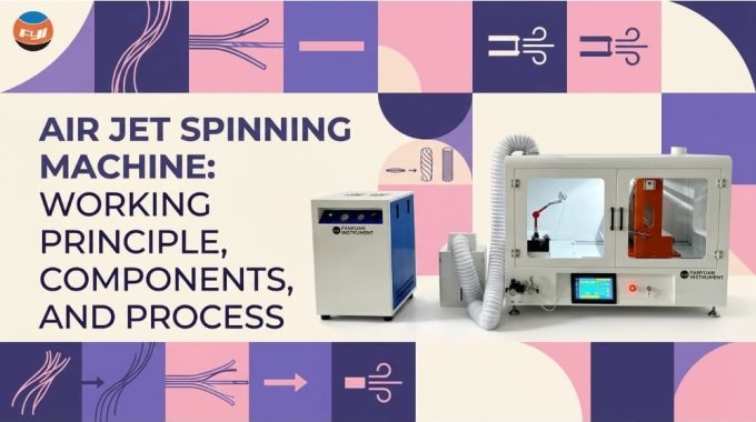
Air Jet Spinning Machine: Working Principle, Components, and Process
Air jet spinning has been developed as a result of DuPont studies in the 1960s.
It was put into commercial use with the development of the first Murata Jet Spinner (MJS) in 1981.
The first generation had two opposing nozzles and created fasciated yarn, appropriate mostly for polyester/cotton mixes.
The technology changed in 1997 with the development of the Murata Vortex Spinner, which replaced the second nozzle with a hollow spindle, enabling the manufacture of 100% carded and combed cotton yarn. In 2009, Rieter developed J 20, followed by J 26 and J 70.
Nowadays, the technology competes with rotor and ring spinners in the Ne 20-60 range, providing yarn at a higher operating speed than any mechanical twisting process.
What Is an Air Jet Spinning Machine?
An air jet spinning machine is a short-staple spinning method that transforms drawn sliver into wound yarn packages using compressed air instead of a rotating spindle to insert twist.
The operation includes drafting, twisting, clearing, and winding in one continuous process.
How It Works in Brief
Sliver is introduced to the four-line drafting system from the creel and is attenuated up to the final yarn size.
The attenuated sliver enters the nozzle assembly, where tangential air jets create a fast-moving vortex around the stationary hollow spindle.
Fiber end fibers splay out, wind the core, and the yarn produced is collected, inspected by the clearer, and wrapped on the cross-wound bobbin.
Air Jet vs. Ring, Rotor, and Friction Spinning
All four spinning processes differ in one basic principle – in the way twist is applied.
The ring spinning process rotates the bobbin; rotor spinning rotates the collecting groove; friction spinning employs perforated drums; and in air jet spinning, there is no rotating part at all.
| Parameter | Ring | Rotor | Friction (DREF) | Air Jet |
| Twist element | Traveler and spindle | Rotor groove | Friction drums | Air vortex |
| Delivery speed | 15 – 30 m/min | 150 – 250 m/min | 100 – 300 m/min | 350 – 500 m/min |
| Typical count range | Ne 4 – 120 | Ne 6 – 40 | Ne 0.5 – 14 | Ne 20 – 60 |
| Yarn structure | Fully twisted | Twisted with wrapper belts | Layered core-sheath | Untwisted core, wrapped sheath |
| Relative tenacity | 100% | 75 – 85% | 50 – 70% | 80 – 90% |
| Process steps from the sliver | Roving, spinning, winding | Spinning only | Spinning only | Spinning only |
Air Jet vs. Vortex Spinning

Vortex spinning is a special type of air jet spinning that employs one nozzle and a hollow spindle to generate true twist, as opposed to the conventional MJS system, which makes use of two nozzles and false twist.
Murata calls their machines Vortex, but Rieter and Savio call a single-nozzle machine an air jet. At present, the terminology is used loosely to denote the same hollow-spindle production system.
Working Principle
In air jet spinning, the leading end of the fibers is drawn into the hollow spindle with the trailing ends being separated from the strand and spun about the hollow spindle inlet due to the spinning effect of the airstream.
In this process, the core fibers remain parallel and untwisted, cohesion arising entirely from the sheath.
The False Twist Principle
In the earlier two-nozzle MJS, the first nozzle gives a false twist in one direction, and the second, powerful nozzle provides a false twist in the opposite direction.
False twist added beyond the drafting zone flows backward. It nullifies itself, as a result of which the core untwists, and the edge fiber that detaches itself from the front roller nip remains wrapped in the yarn, forming an unbalanced and weak yarn of short staple cotton.
How the Air Vortex Forms
The compressed air enters the nozzle block through three or four tangentially oriented injectors mounted within a cylindrical cavity.
The air jets form a fast swirl in a high velocity flow, leaving the cavity in an axial direction past the tip of the spindle and creating rotation and suction.
The rotational speeds inside the cavity are equivalent to the twist rates of false twist above one million twists per minute. There is no mechanical element that could replace the air.
Wrapper Fibers and Real Twist
As the filament emerges from the front roller nip, the front fiber ends are drawn into the spindle orifice by axial suction, while the rear fiber ends lose their connection with the nip; they are spread by centrifugal force and rotate around the spindle head.
Since the core fiber has been rotating into the spindle at this time, this results in the formation of a real twist of the rear fiber ends on the surface of the core fiber.
Single vs. Dual Nozzle
A dual-nozzle machine produces a false twist in the yarn and requires a blend containing a certain amount of artificial fibers to make the strength useful.
A single-nozzle machine with a hollow spindle produces true wrapper twist yarns, can be used with 100% cotton yarns, and offers better tenacity and uniformity. Both currently existing machines are single-nozzle machines.
Why No Spindle Is Needed
Ring spinning is restricted by the traveler friction and by the balloon force created by the high speeds of rotation of the ring spinning frame.
Rotor spin is limited by bearing service life and centrifugal forces acting on the rotor. Because there is no twisting mechanism in air-jet spinning, the delivery speed is limited solely by fiber properties.
Main Components
An air jet spinning machine comprises the following parts: a sliver creel, a drafting mechanism, a nozzle block with a hollow spindle, a yarn clearer, a winding mechanism, compressed air, and a suction supply.
All parts are controlled from the control panel with traveling piecing robots. Modern machines have up to 200 spinning heads located on both sides.
Creel and Sliver Feed
Arrangements can be made below or behind each rotating mechanism.
The sliver moves via a guide and condenser to the drafting mechanism entrance, where a sliver sensor stops the position if breakage or exhaustion occurs.
Drafting System
Four-over-four apron drafting mechanism creates a total drafting of about 150 to 350, starting at 3-5 ktex sliver going directly to the count.
Since there is no roving phase, drafting accuracy plays an essential role in controlling yarn evenness compared to ring spinning.
Air Jet Nozzle
The nozzle mechanism consists of injector bores and a vortex chamber.
It is a disposable precision component; the geometry and surface finish of the bore are responsible for the wrapper creation, and nozzle wear results in strength degradation.
Hollow Spindle and Needle
The spindle is a stationary ceramic or hardened steel tube with a cone-shaped head. The needle, which protrudes from the fiber guide mechanism, is located on the spindle entrance.
Yarn Clearer
The clearer either optical or capacitive checks for any areas where the yarn is too thick or too thin, neps, or foreign matter, and cuts them out and automatically splices the yarn.
Piecing Robot
Robots move around the machine and mend broken ends by threading the yarn back into the spindle, resuming drafting in synchronization with the withdrawal rollers and making the splice. The entire piecing process is completed in 20 to 30 seconds.
Winding Unit
The yarn is wound directly on the cross-wound packages of up to 6 kg on a grooved drum with antipatterning control. The waxers are provided for knitting yarns.
Air Supply and Suction
The air supply system has a dedicated compressor that supplies filtered air to the machine’s distribution header, and air pressure is controlled individually for each section.
A separate vacuum system removes any trash, fly, or fiber waste produced by piecing.
Control Panel
The panel is used to set the draft ratios, delivery speed, nozzle pressure, and clearing parameters, and to record the efficiency and end-down per position.
The Spinning Process
The spinning process by air jets starts with opening the bales in the blowroom, followed by carding, combing, and drawing, and ends at the spinning machine, where spun slivers are directly converted into wound-up yarn.
Quality of preparation is crucial since, in the absence of a roving frame and doubling in spinning, any irregularities in the feed sliver will show up in the yarn.
Blowroom
Opening, cleaning, and blending remove any trash and dust. Short fibers and neps introduced during this stage result in reduced wrapper quality and increased end-downs.
Carding
Separation of individual fibers and additional removal of trash produces a card sliver 4-5 ktex. Carding should be optimized to produce fewer neps; neps interfere with the proper transfer of fibers into the spindle.
Drawing
Two-stage drawing with autolevelling in the second stage improves evenness and degree of parallelization. Parallelization for air jet spinning is higher than for rotor spinning because fiber orientation is critical for determining which fibers act as wrappers.
Combing
Combing is necessary for cotton yarns at 12-20% noil removal. The content of short fibers exceeding 5% in weight substantially increases ends-down and decreases tenacity.
Drafting
The drafting stage reduces the sliver to its final size right before the nozzle. The distance between the front roller point and spindle entrance is kept close to the staple fiber length.
Yarn Formation
The leading ends of the fibers are fed into the spindle; the trailing ends are drawn around the vortex. The yarn formation process takes place within several millimeters of the spindle point.
Clearing and Winding
The yarn goes past the clearer and winds up on the package. The flaws are separated and spliced without any operator’s interference.
Automatic Piecing
At the end of the process, the stop occurs; the robot feeds the yarn end into the spindle, synchronizes the feeding and delivery, and continues operation.
How Compressed Air Creates Yarn
Air as the Twisting Element
The yarn is produced by the action of compressed air on the fiber ends, causing the formation of a high-speed vortex that separates the fiber ends from the drafting strand. It winds them spirally around a parallel core fed into the hollow spindle.
Air accomplishes three functions at once – twisting, transporting, and tensioning the fibers.
Nozzle Geometry
The injector diameter, the angle of the tangential entry, and the clearance between the chamber and spindle define it.
Nozzles are selected depending on the type and count of the fiber; nozzles for viscose will be ineffective for combed cotton.
Air Pressure and Yarn Structure
Typical working pressure varies from 0.4 to 0.6 MPa. Increased pressure results in tighter wrapping and higher yarn strength until the critical point is reached; after that, fiber loss and hairiness occur.
At low pressure, softer, bulky yarns are produced with lower strength.
Air Consumption
Compressed air is the main energy expense during the process and accounts for the majority of the machine’s overall power consumption.
Consumption ranges from 1 to 2 Nm³/h per spinning station; thus, for a machine with 200 stations, considerable compressor capacity is required.
Air Quality and Filtration
Air should be dry, free of oils, and finely filtered. Moisture and oil contamination cause buildup in the injector bore, which distorts the vortex and gradually deteriorates yarn quality.
Common Air-Related Faults
Faulty or clogged injectors result in poor, hairy yarn formation in specific areas. Pressure loss with an undersized header results in quality variations at the beginning and end of the machine.
Impurities in the air cause cyclical end-down problems, which are often mistaken for drafting problems.
Yarn Quality

Air-jet spun yarn has a characteristic core-sheath structure, providing low hairiness, abrasion resistance, excellent pilling properties, and 10-20% lower tenacity than ring-spun yarn of the same count.
Fabric exhibits a well-defined surface, quick moisture transport, and minimal shrinkage.
Yarn Structure
Yarn core is made of nearly parallel and untwisted fibers; yarn sheath comprises wrapper fibers, lying in a steep helix angle.
Hairiness and Abrasion Resistance
The protruding fiber ends are bound within the sheath, and therefore, the S3 hairiness value of such yarn is much lower than that of ring-spun yarn.
The close sheath also makes the fabric resistant to surface fibrillation, thereby reducing pilling in knits.
Suitable Fibers
Viscose, modal, lyocell, and polyester perform excellently. Cotton fibers must be combed, with a minimum staple length of 28-30mm and a low short-fiber percentage.
Blending cotton with man-made fibers improves running performance.
Limitations
It has a limited count range compared to ring spinning, and counts lower than Ne 16 are not suitable. Preparation for spinning is very critical.
The fabric handle is stiff, which is a disadvantage where a softer hand is required.
Conclusion
This method uses a compressed-air vortex to twist the sliver into yarn rather than mechanical twisting. It produces wrapper yarn with a speed of 400-500 m/min in a single operation.
This method yields low hairiness and high abrasion resistance but requires highly combable, long-staple slivers.
FAQs
What Yarn Counts Are Possible?
The commercial range is from around Ne 20 to Ne 60. Man-made fiber yarns can be finer, up to Ne 80; counts Ne 1 are not economical.
How Much Air Does It Use?
About 1 to 2 Nm³/h per spinning position at 0.4-0.6 MPa pressure, being the major energy consumer in terms of air compression in the machine.
Is the Yarn Stronger Than the Ring Spun?
No. Tenacity is usually 10-20% lower than that of the ring-spun yarns of the same count, although evenness, hairiness, and abrasion resistance are higher.
What Does a Machine Cost?
Although capital costs per spinning position are high, productivity is 15-20 times greater than ring spinning, reducing investment costs per kg of yarn. Costs depend on the configuration.
Can It Spin 100% Cotton?
Yes, with the use of single nozzles with adequate staple length of combed cotton yarns. Carded cotton is also possible, resulting in reduced tenacity and an increased ends-down rate.