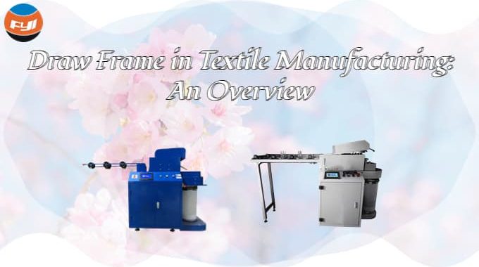
Draw Frame in Textile Manufacturing: An Overview
Contents
What is meant by draw frame?
The draw frame is a spinning machine that converts multiple carded or combed fiber strips into fiber strips of a certain grade.
The role of draw frame in textile
The role of draw frame in textile is to enhance the internal structure of the sliver, enhancing its long-section homogeneity. At the same time, decrease weight unevenness, straighten and parallelize the fibers in the sliver, reduce hooks, fulfill the fineness criteria, and ensure that different types or quality of raw materials mix uniformly to reach the desired mixing ratio.
The structure of the draw frame
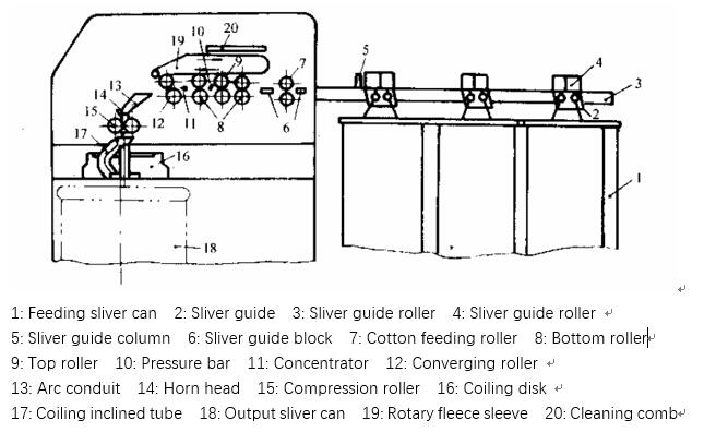
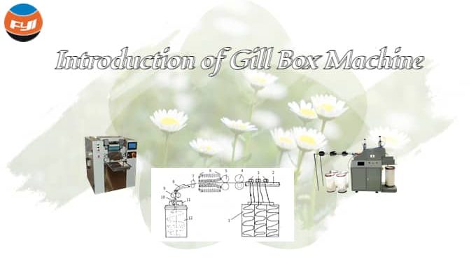
The draw frame usually consists of a feeding part, a drafting part, a sliver part and some automatic devices. The following is the draw frame machine diagram.
Feeding part
The entire feeding section is made up of a feeding container, a sliver guide roller, a sliver guide platform (or raised frame), and a cotton feeding roller, among other things. The sliver is guided out of the feeding can by the sliver guide roller and the sliver press roller and directed in a certain path to the sliver guide platform. The guiding roller is near to the feeding can on the high-speed draw frame, and the sliver is pushed to the platform and then sent to the drawing mechanism by the feeding roller. Positive feeding prevents inadvertent elongation and avoids turbulence in the outgoing sliver.
Sliver rack: This item is normally situated at the machine’s feed intake and is used to insert the sliver or chemical fiber sliver to be treated while also ensuring uniform material delivery.
Drive Section: This section usually consists of one or more sets of gears and chain mechanisms that transport the sliver to be processed to the feed belt and rollers.
Feeding belt: This component consists mostly of two moving belts that can draw the sliver to be processed from the sliver creel to the feeding roller while maintaining a constant tension and speed. To guarantee that the sliver enters the machine uniformly.
Feed rollers: This segment is made up of numerous rollers that draw the sliver from the feed belt into the machine interior while also controlling its length and amount.
Electronic control system: This is an important portion that regulates the feeding part’s operating state and process, as well as monitors the operational status of the equipment and control parameters such as adjustment.
Drafting part
It is composed of drafting mechanism and automatic cleaning device.
There are several varieties of drafting mechanisms, which are mostly governed by the combination of drafting rollers and other control components. There are three combinations of upper and lower drafting rollers, namely, one up and down (one top roller and one bottom roller), one up and two down (one big top roller and two bottom rollers) and two up and one down (two top rollers and one bottom roller).
Linear drafting is when each pair of rollers is one up and one down and the yarn is constrained in the same plane. Curve Drafting is when part of them belong to the combination of one up and two down or two up and down, such as three up and four down type, and so on.
The cleaning device’s role is to remove the flies and dust adhered to the surface of the top roller and roller in a timely manner, preventing piles and falling into the sliver to generate yarn flaws, which is especially critical for high-speed draw frames.
Strip part
Including bunching mechanism, bell mouth, squeeze roller, coiler, sliver can base, etc.
A clustering device, a clustering roller, and an arc duct make up the clustering mechanism. The bundler is a novel metal collector that is positioned in front of the front drafting roller and has a big entry and a tiny exit. The role is to gather the cotton web into a belt in time, to minimize side fiber loss and confusion when the cotton web is produced at high speed, to promote fiber cohesion, and to eliminate the phenomena of winding rollers and broken strips. The bundle roller’s duty is to compress the cotton belt and stabilize the fiber’s straightness. The arc-shaped conduit is a semi-closed or closed copper conduit, which guides the cotton tape smoothly into the bell mouth to prevent the cotton tape from breaking or blocking the bell mouth.
The bell mouth and compression roller squeeze the cotton belt into a tight and smooth sliver, which reduces unintentional elongation when drawn out and increases the capacity of the sliver container. The compressed sliver enters the coiler’s inclined tube gear and is coiled into the sliver container in a cycloidal form. To adapt to the processing of chemical fiber raw materials, the sliver section uses the coiling disc of the spiral space curve inclined tube, which may avoid the coiling inclined tube from clogging.
Furthermore, the high-speed draw frame must be outfitted with high-sensitivity self-stop devices, such as winding rollers and broken ends in front of the machine, automated stops for broken ends and missing strips, and safety self-stop devices behind the machine. The draw frame’s braking device can avoid quality issues such as yarn flaws and machine component loss caused by the inertia of high-speed parts after shutdown.
What is the process of draw frame?
The work flow of a draw frame generally includes the preparation of the sliver, the flow into the machine and the collection of the processed sliver.
Preparation of the sliver
Before entering the drawing frame, it is necessary to place multiple cotton slivers or chemical fiber slivers flat on the sliver laying table, and ensure that their length and thickness are equal, so as to get a more uniform mixing inside the machine. Likewise, the sliver needs to be treated to keep its surface clean and free of impurities.
The process of entering the machine
Once all the slivers are ready, they are fed to the infeed system of the draw frame. Here, the slivers are fed into a set of dosing feeders to ensure that each sliver fed to the machine is a consistent number and length. Next, the sliver enters the front roll unit, where, through a series of take-off rolls, the thickness of the sliver is effectively mixed and inhomogeneous parts are removed in the process.
Merging of strips
After the front roll treatment, the sliver goes to the back roll unit where it is processed into strips of continuous fiber. Here, because the speed of the latter two sets of rollers is slower than that of the first two sets of rollers, the density of the sliver can be adjusted, and the tension between the integral roller and the speed difference roller will flatten the fibers inside the sliver, and at the same time remove fluff balls and other irregularities. clean substance.
Collect silvers
Once passed through the back roller equipment, the sliver has been merged and the sliver has a higher softness, water absorption and air permeability. At this point, the sliver will flow down the conveyor belt from the top of the machine and be wound into a circle on the base. Before the slivers are sent out of the net machine, they are inspected to ensure that they are of the expected quality.
In summary, the work flow of a draw frame is complex and requires several steps to complete. Through the coordinated operation of key equipment such as quantitative feeder, front roller equipment, and rear roller equipment, multiple slivers can be merged quickly and efficiently, providing more uniform, tougher and elastic raw materials for the subsequent spinning process .
Your writing is so poetic and lyrical. I could read it for hours on end.
These practical tips provided in the blog post are incredibly useful.
Both entertaining and educational, this blog strikes the perfect balance.